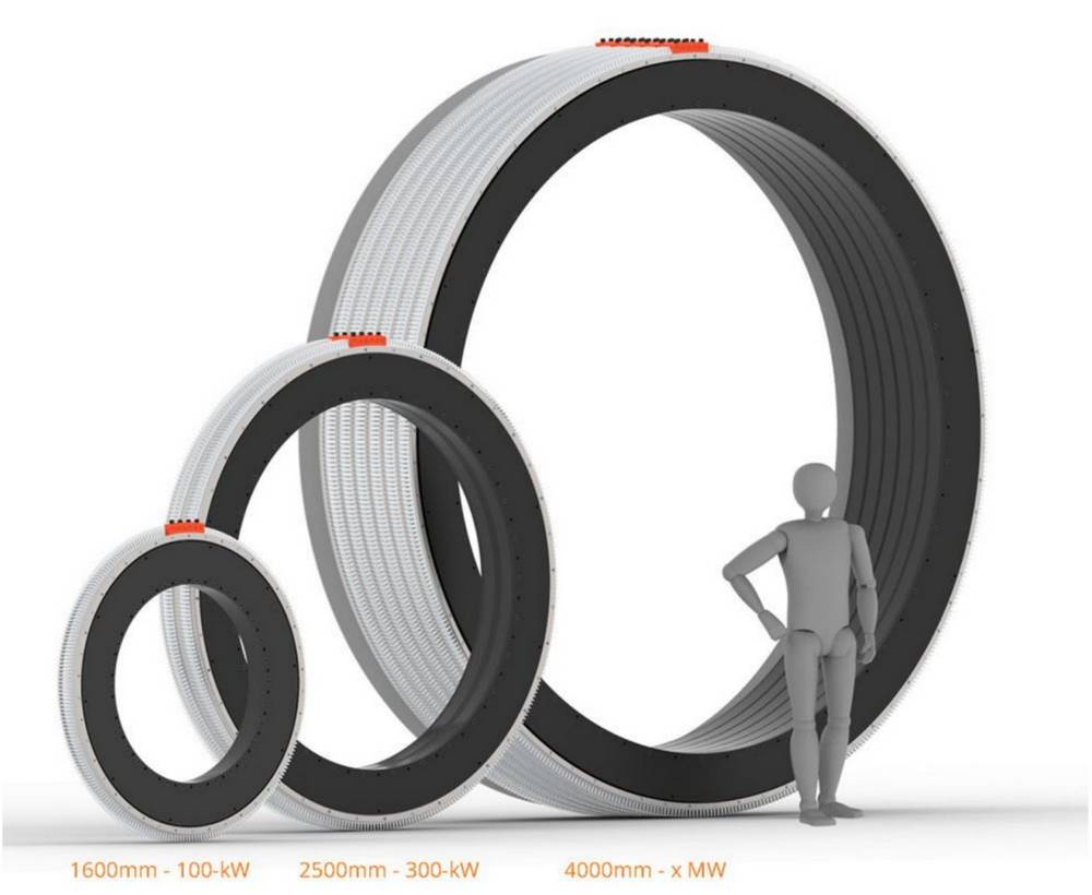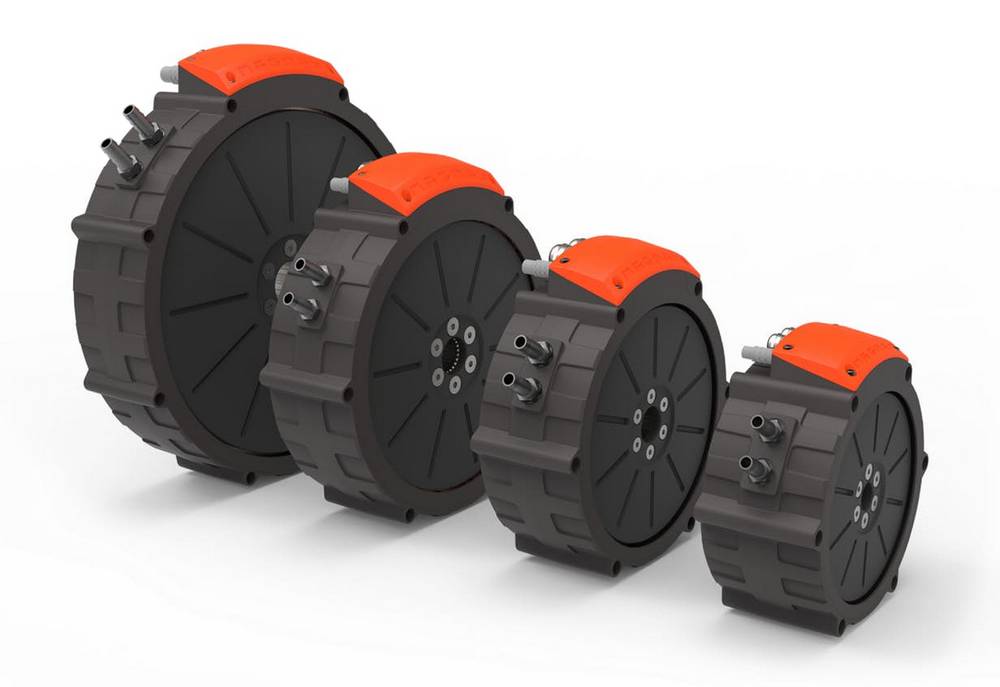

In terms of PCB motors, this arrangement means a printed circuit board as stator, containing all windings, and a permanent magnet rotor stacked on top of each other. For axial configurations, in contrast, the torque increases proportional to the cube of its outer radius . The maximum torque generated by a radial-flux machine is proportional to its volume, i.e., to the square of its rotor radius times its length. The main functional principle is the same as for radial-flux machines. For this type of electric motor, the main magnetic flux in the air-gap is arranged in axial direction, so, parallel to the rotational axis. Axial-flux machines, in contrast, have a winding design suitable for PCB printing. Some research on the use of flexible PCBs for radial-flux machines is presented in and . Such windings could hardly be achieved by standard PCBs. For these machines, the windings form a three dimensional shape in the stator. The manufacturing processes for these motor designs are well known and have been established in industrial manufacturing for a long time . Most of the commonly used electric motors are of radial-flux type, this means that the main magnetic flux in the air-gap is aligned in radial direction.

Increased flexibility in winding design, while at the same time decreased manufacturing costs are one of the main goals. The main idea of PCB motors is to replace conventional copper wire windings of standard electric motors with printed circuit boards.


 0 kommentar(er)
